Knowledge


↑ Solidot slice serial communication moduleXB6S-C01SP
Temperature meters and weighing meters used in the food and medical industries, pressure gauges used in the 3C industry, and frequency converters most widely used in the automotive, lithium battery and logistics industries all communicate via the Modbus protocol. In practical applications, however, they cannot communicate directly with the fieldbus and require a module for relaying, in order to read the current device status or change the device output status.
This is precisely the function of the Solidot slice serial Communication module XB6S-C01SP: it can convert other bus protocols into a serial communication protocol. Based on the Modbus communication protocol, this article explains in detail the Operating instructions for the XB6S-C01SP module within the Modbus protocol.
1. Definition of the Modbus protocol
The Modbus protocol is a general-purpose communication protocol that is already widely used in today's industrial control field. Through this protocol, controllers can communicate with each other, or a controller can communicate with other devices via a network (such as Ethernet).
2. Function of the Modbus protocol
A protocol is generally used to specify the conditions required for information transmission — the rules established to enable communication. For example, A needs to query B to obtain some status information from B. A sends a set of data to B: 12345. After receiving this set of data, B replies to A: 54321. This completes a data Exchange, but such data is not very convenient to transmit using ordinary language or characters.
At this point, transmission in numerical form becomes particularly important, but the meaning of each number must be defined in advance. The purpose of defining a protocol is to enable two parties to understand a transmitted set of data according to that protocol, and from this the Modbus serial communication protocol was derived.
3. Modbus protocol modes
In practice, Modbus transmission is divided into 3 methods:
1. Modbus RTU
2. Modbus ASCII
3. Modbus TCP
These three protocols all actually belong to the Modbus protocol, because the three message formats are generally consistent. Among them, the RTU form is the most common for serial ports, while TCP refers to transmission over a network cable.
4. Modbus protocol communication method
The Modbus protocol is a master-slave communication, meaning that a "question-and-answer" exchange is required. During communication, the slave only responds after the master sends a request command; if the master does not send one, the slave will not respond either. This is also a limitation of Modbus. When this "question-and-answer" method can occur with one master corresponding to multiple slaves, each slave must be distinguished by giving each slave a "name", and thus the slave Station number came into being.
5. Specific expression format of the Modbus protocol
Modbus protocol frame structure = address + function code + data + checksum
1. Address: this is the slave "name" mentioned earlier — the slave Station number
2. Function code: this specifies what the command does — whether it is a query or an execution command
3. Data: used to specify the location information for executing a specific command
4. Checksum: since errors may exist in the data area, a checksum is calculated over all the data to verify the correctness of the transmitted message
6. Modbus protocol examples
Now that we understand the structure of the Modbus protocol, let us examine two examples — a read and a write — for analysis.
[example 1] Reading holding registers (03)
Send: 01 03 00 00 00 02 C4 0B
Receive: 01 03 04 A0 B0 C0 D0 88 48
Send: Slave Station number (01) + read holding register function code (03) + Modbus start Register address (00 00) + number of Registers to read (00 02) + Modbus checksum (C4 0B)
Response: Slave Station number (01) + read holding register function code (03) + total number of bytes read, 2 x number of registers (04) + read register data content (01 02 03 04) + Modbus checksum (88 48)
[example 2] Writing holding registers (16)
Send: 01 10 00 10 00 03 06 01 02 03 04 05 06 5D D3
Receive: 01 10 00 10 00 03 81 CD
Send: Slave Station number (01) + write holding register function code (10) + Modbus start Register address (00 10) + number of Registers to write (00 03) + total number of bytes to write (06) + write register data content (01 02 03 04 05 06) + Modbus checksum (5D D3)
Receive: Slave Station number (01) + write holding register function code (10) + Modbus start Register address (00 10) + number of Registers to write (00 03) + Modbus checksum (81 CD)
7. XB6S-C01SP module Operating instructions
From the detailed explanation above, we now know how to use the Modbus protocol. Next, we need to use the XB6S-C01SP module instead of a serial port to send messages, enabling information transmission between devices. The master uses the XB6S-C01SP module and connects to the PC via a serial communication cable. We will demonstrate by using the function code messages from the examples above to control the ModbusSlave software (Modbus slave simulator) and to read messages with a serial debugging assistant.
1. First, perform configuration. Here, the EtherCAT protocol is used as an example, together with the Solidot XB6S-EC protocol Coupler XB6S-EC2002:

2. Configure the module parameters, setting the function, baud rate, stop Bit, parity bit and other parameters to match those of the serial device:
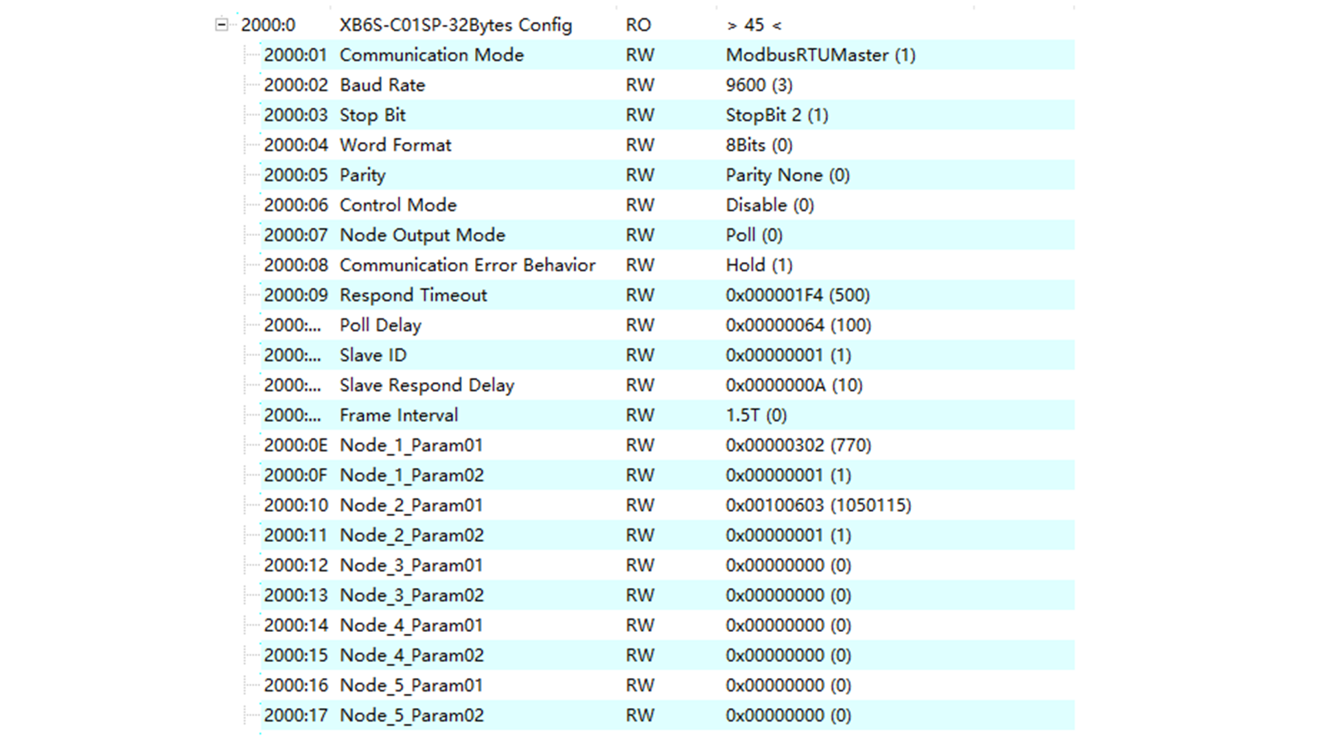
The definitions within the node parameters are rather special and are the most important part of the configuration parameters. Fill in the required function code, address and other data according to the calculation table to obtain the final calculation:

Node_1_Param01 (302)
Node_1_Param02 (1)
Node_2_Param01 (1000603)
Node_1_Param02 (1)
3. Enter the parameter data to be sent:
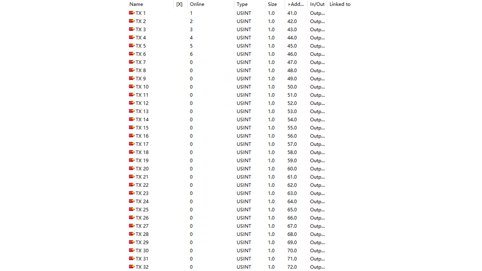
After setting the parameters, write them to the module. When you open the serial port assistant, you can see that the module automatically compiles the example message above and sends it out through the serial port.
4. Open ModbusSlave and switch to Holding register. The data sent by the module can now be read after address (00 10), and data A0 B0 C0 D0 can be written into the address. The data can also be read on the Coupler. Through the above operations, the XB6S-C01SP module replaces the need to manually write messages, enabling communication with the device. The above is a detailed introduction to the operating instructions of the Solidot Slice serial communication module XB6S-C01SP under the Modbus protocol.
If you have any questions, please feel free to contact us. We will be happy to serve you!