Knowledge

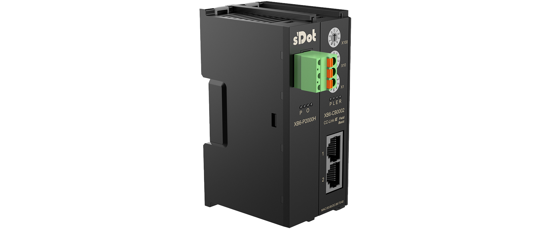
↑ Solidot CC-Link IE Field Basic Slice I/O Coupler KitXB6-CB2002ST
When the Solidot XB6 series I/O modules are adapted to a CC-Link IE Field Basic master, each channel of a digital I/O module occupies 1 bit, and the fixed data length is 4 bytes (= 32 bits), which is the data length of one XB6-3200A. Therefore, digital modules use the same "32-bit mold".
1. According to this rule, the following two cases can be distinguished. Let us first look at digital I/O modules
1. Point allocation for pure-input digital I/O modules
XB6-1600A occupies 32 points, but actually uses the first 16 points; the last 16 points are unused (reserved). XB6-0800A actually uses the first 8 points, and the last 24 points are unused (reserved). The same applies to output modules.
2. Point allocation for mixed input/output digital I/O modules
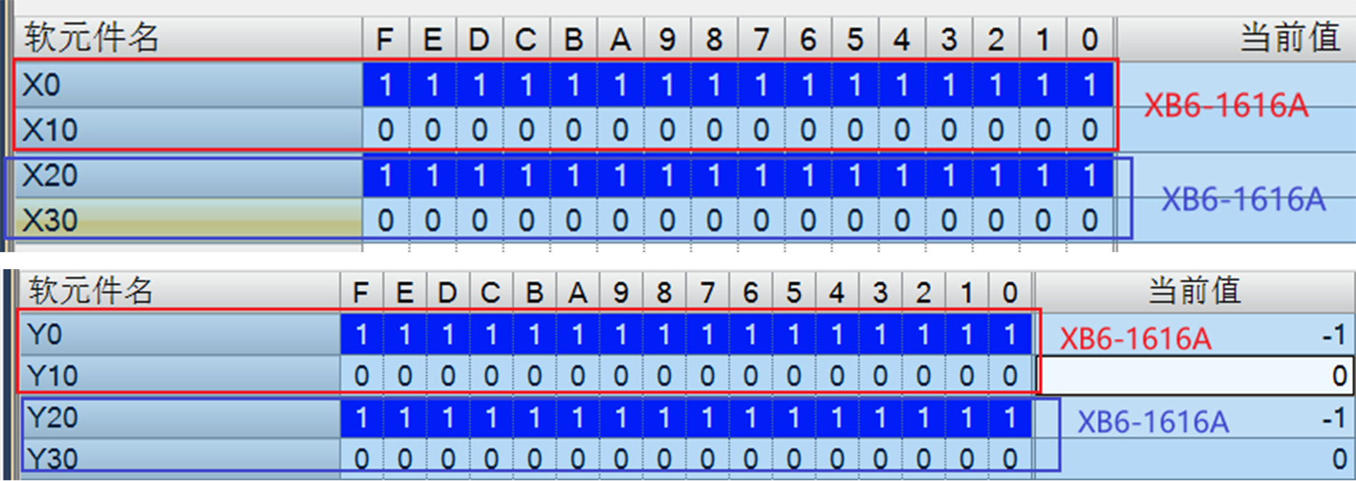
For XB6-1616A, the Upstream RX occupies 32 points, actually using the first 16 points, with the last 16 points unused (reserved); the Downstream RY occupies 32 points, actually using the first 16 points, with the last 16 points unused (reserved). Therefore, when two XB6-1616A modules are connected together, the Upstream RX of the second I/O module must be offset by the number of unused (reserved) points of the previous I/O module, as shown in the figure below:
2. Now let us look at analog I/O modules
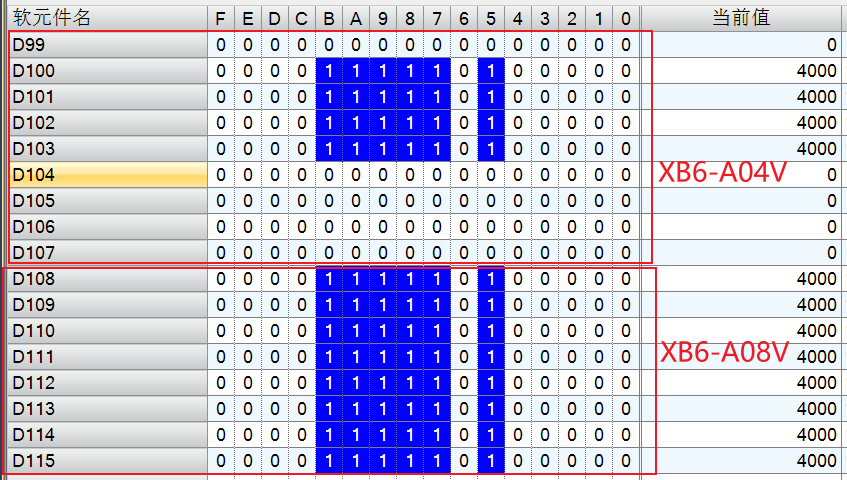
The analog I/O modules of the Solidot XB6 series include XB6-A80V, XB6-A40V, XB6-A08V, XB6-A04V, XB6-A80I, XB6-A40I, XB6-A08I and XB6-A04I. In actual use, each channel occupies 1 word, so an 8-channel analog I/O module occupies 8 words, and a 4-channel analog I/O module is the same as an 8-channel analog I/O module, also occupying 8 words. Therefore, XB6-A40V occupies 8 words, actually using the first 4 channels, with the last 4 channels unused (reserved). When the Coupler XB6-CB2002ST connects one XB6-A04V and one XB6-A08V, the mapping address arrangement is as shown in the figure below:
note:
1. XB6-A80TM and XB6-A40TM follow the same principle;
2. The mapping addresses of function modules such as XB6-P04A do not follow the above rules. For details, visit the Solidot official website, search for the required model, and refer to the relevant user manual. Quick access to the function module collection page: https://www.solidotech.com/cn/slice-io/function-module