Knowledge

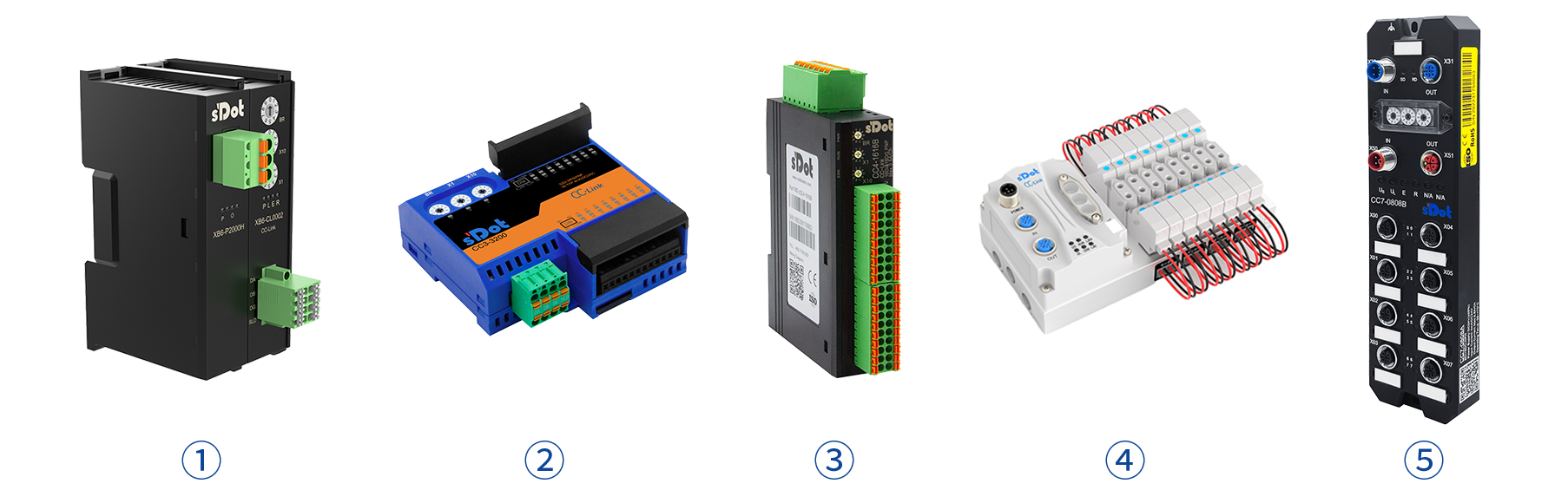
↑ Recommended Solidot CC-Link series products
figure ① Solidot CC-Link Slice I/O Coupler Kit XB6-CL2002ST
figure ② Solidot CC-Link horizontal I/O CC3-3200
figure ③ Solidot CC-Link vertical I/O CC4-1616B
figure ④ Solidot CC-Link Fieldbus Valve terminal C2S-CL-08B-S01
figure ⑤ Solidot CC-Link IP67 I/O CC7-0808B
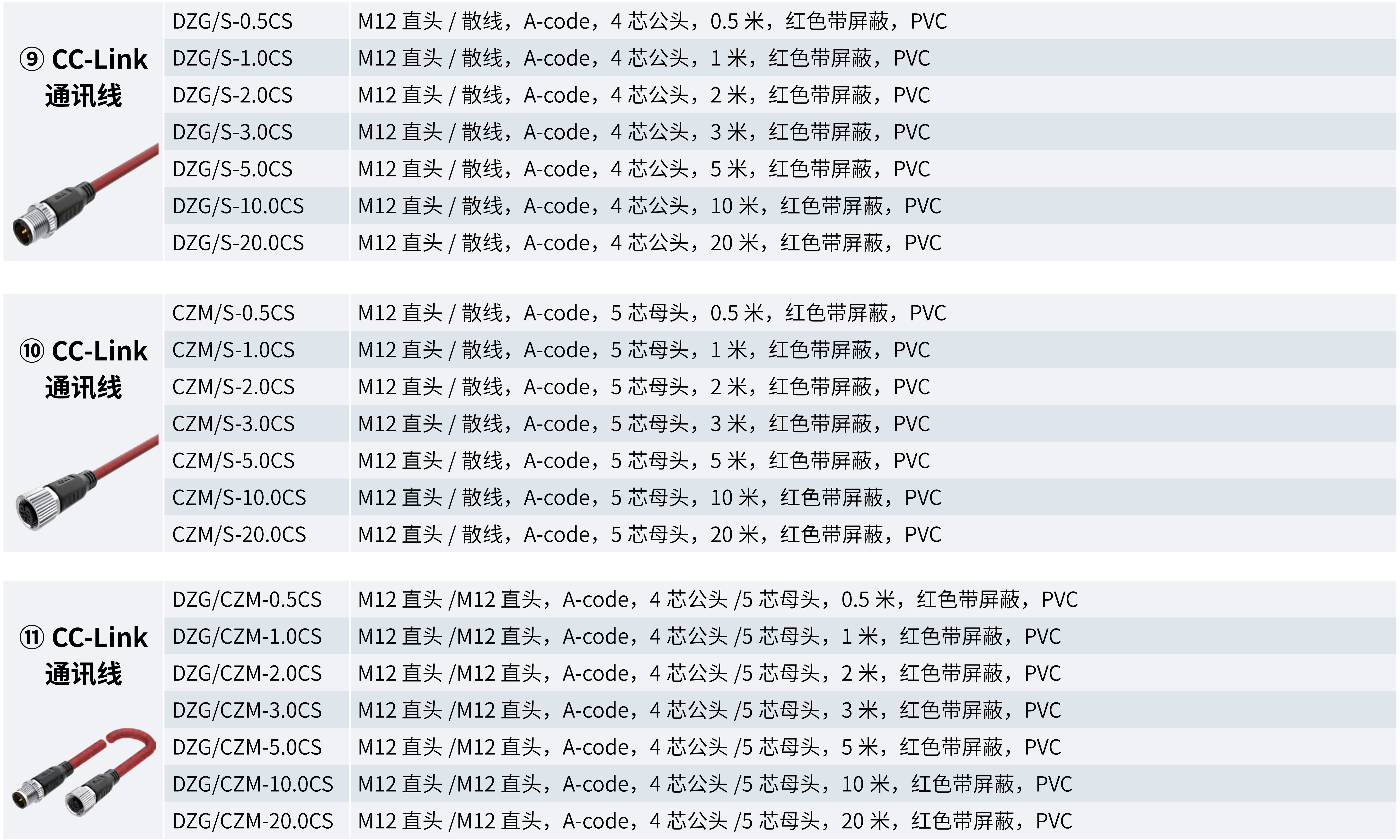
↑ Solidot CC-Link communication cable
Suitable for wiring of Fieldbus Valve terminals and CC7 series I/O modules
1. Overview of common problems
*After power-on, a large number of modules go offline;
*After starting the Servo Motor, a large number of modules go offline;
*modules drop offline and reconnect persistently or randomly on the line;
*At low baud rates, the delay is > 100 ms; at high baud rates, modules go offline.
2. Analysis of cable-related causes and key points to note
There are generally two main causes: 1. poor cable quality; 2. non-compliant cable routing. See the key notes in the relevant screenshots of the "CC-Link Wiring Specification" below.
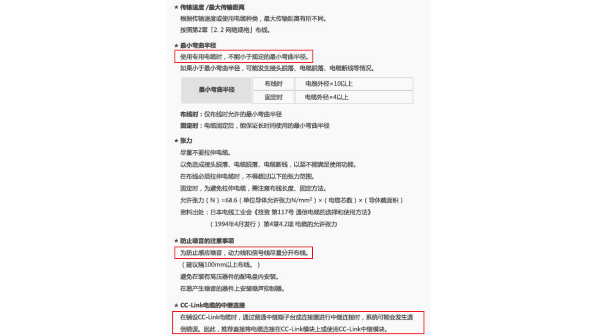
Based on the above, the following points must be observed during wiring:
*Use CC-Link certified cable that is CC-Link Ver.1.10 compatible (characteristic impedance 110 Ω, terminating resistor 110 Ω)
*Route communication cables separately from power cables; the clearance between ducts must be > 20 cm
*Without a Mitsubishi T-Branch connector, only station-to-station series connection is possible
*terminal blocks available on the market are highly prone to crosstalk and packet loss, which degrades communication quality. It is recommended to use the corresponding FA sensor connector NECA4202 (IEC947-5-2) products
note: NECA is the abbreviation for the Japan Electrical control Equipment Industry Association; NECA4202 (IEC947-5-2) represents its relevant standards.
*For signal repeating on non-T-branch lines, avoid using terminal blocks where possible
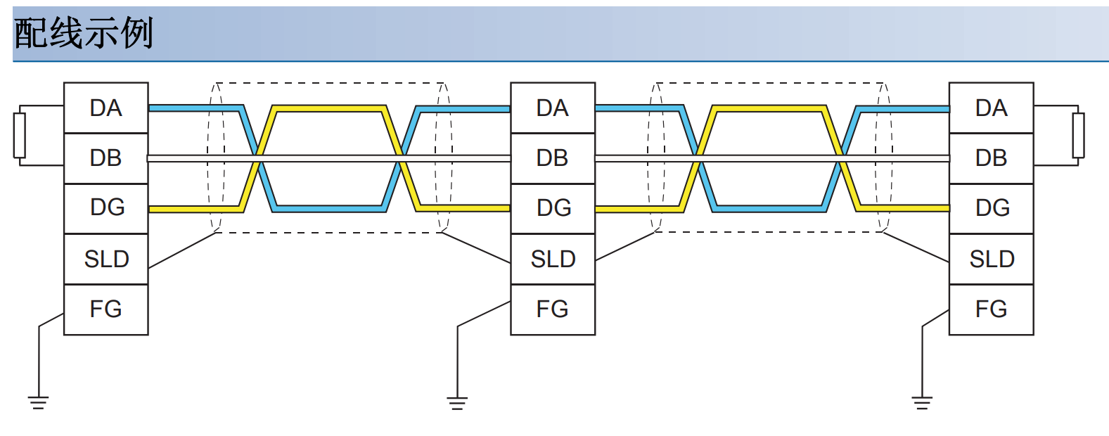
*Connect 110 Ω terminating resistors to both ends of the trunk line
note: In a CC-Link network, the purpose of the terminating resistor is to eliminate signal reflection and ensure clear and reliable network data transmission. Since CC-Link is a digital bus protocol based on serial communication, it uses differential signal lines similar to coaxial cables to transmit data, and such lines cause signal reflection. To minimize the effect of signal reflection on signal transmission, a terminating resistor matched to the characteristic impedance of the signal must be installed at both ends of each CC-Link bus. During normal operation of the entire network, these resistors help ensure the stability and reliability of network data transmission and reduce interference and bit error rate issues. Therefore, the terminating resistor plays a very important role in a CC-Link network. The relevant diagrams are shown below—
3. Cable troubleshooting methods
With the power off, measure the line impedance between DA and DB. If the resistance is 55±3 Ω, it is normal (this can be measured directly between DA and DB on the PLC side). Otherwise, check whether any device on the line has an abnormal resistance value. The common cases are as follows:
*A module's DA/DB/DG has broken down, causing its own resistance to drop sharply (for Solidot I/O modules, the resistance between DA and DB is 25.4 KΩ; for Mitsubishi I/O modules, it is 80 KΩ). A broken-down module is recommended for direct replacement;
*The CC-Link cable is abnormal; the cable's resistance to ground!= ∞. Direct cable replacement is recommended;
*The total on-site cable length exceeds the maximum communication distance at the current baud rate. Reduce the baud rate or re-route the cabling.